
Photonic Antennas with Integrated Optical Transducers
Background
Distribution of multiple wireless services including GSM/UMTS, TETRA and WLAN via installed fibres in buildings has become a commercial reality because of the broadband, low-loss and modulation format agnostic features that the radio-over-fibre technique offers. Distributing multiple services in a radio over fibre system also centralise the management of telecom and network equipment. Photonic antennas find applications in such in-building scenarios by acting as the interface between the installed fibre infrastructure and the wireless service users. The cost of manufacturing such photonic antennas can potentially be reduced further if they are integrated directly with the optoelectronic components performing the optical-electrical and electrical-optical conversions, and this has been the motivation and the subject of the project.
Photonic Antennas has been a collaborative project between University College London (UCL), Queen Mary University of London (QMUL) and Rutherford Appleton Laboratory (RAL). UCL has been responsible for the design, development and fabrication of the Asymmetric Fabry-Perot Modulator/detector (AFPM) which is used as the key optical transducers functioning simultaneously as an optical intensity modulator and a photodetector. QMUL has been responsible for designing and fabricating a ring of Electromagnetic Bandgap (EBG) and non-EBG patch antennas. RAL has been responsible for developing a technology to package the AFPM from UCL with a connectorised optical fibre pigtail which is critical if the device is to be deployed outside the laboratory environment. RAL has also been responsible for integration of the AFPMs with the antennas from QMUL resulting in the ultimate photonic antennas.
Key Advances and Supporting Methodology
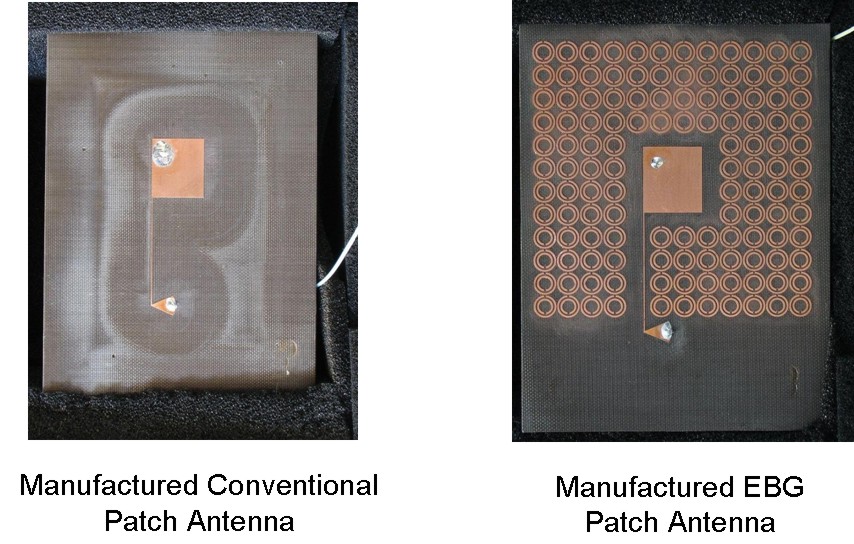
Design of single element non-EBG and EBG antennas
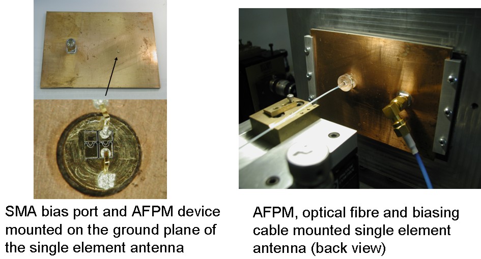
Critical to the integration of photonic antenna are advanced packaging techniques and enhanced antenna design. Since a solid ground plane is required by the AFPM device to be mounted upon, as well as to make the fibre alignment more stable, planar patch antenna is chosen to be developed. In order to tackle the harmful backward radiation, some hybrid structures combining the antenna and the Electromagnetic Band Gap (EBG) enhancement are investigated.
The EBG structures have multiple frequency bands that prohibit wave propagation and such stop bands are basically determined by the periodicity of the structure. In the single element EBG antenna design, an array of Split Ring Resonators (SRRs) is designed to encircle the conventional circular polarized patch antenna. The SRR can be considered as a planar EBG structure, with the bandgap coincides with the antenna resonance.
There are three critical requirements for the single element antenna design:
1) The antenna should be designed at 100O at 5.2GHz in order to match the characteristic impedance of the AFPM device. The impedance matching is done by adjusting the feeding position on the patch along the diagonal line.
2) A DC biasing network is attached to the antenna to provide DC voltage to operate the AFPM. In order to minimize the radiation disruption caused by this irregularity, the DC feed line is optimized to be very narrow (0.2mm) and ended with a radial stub. By properly tuning the length of the feed line and the stub shape, the impedance of the DC biasing can be adjusted to a high level, thus reduces the current induced.
3) T he SRR EBG structure is chosen to tackle the circular polarization. Four rolls of SRRs are placed surrounding the antenna, while a gap is reserved for the DC biasing line. The thinnest gap in the SRR structure is about 0.2mm, demanding an elaborate manufacturing technique. The distance between the radiating patch and the SRR is also optimized to minimize unwanted coupling.
The measured -10dB bandwidth for both antennas are well above the requirement. The return losses are measured at 50O, and then normalized to 100O to estimate the performance with integrated AFPM devices. After normalization, the conventional patch has 1.5GHz (5GHz-6.5GHz) -10dB bandwidth; while the EBG one possesses even wider bandwidth.
The radiation pattern of the EBG antenna at the broadside is improved by about 2dB, whilst the backward radiation is suppressed by more than 5dB around the directions of -135 to -90 degrees. This can be explained that the SRRs reflect the incident wave in an in-phase manner at the operating frequencies, thus reduce the backward radiation and boost the broadside gain. At the other side of the antenna, around +90 to +135 degrees, the radiation level remains similar to the conventional antenna. Obviously, this is due to the biasing stub that is located within the defect of the SRR structure, since the patterns are measured linearly in the vertical axis of the antennas.
For more information on our research, please contact Prof. Y. Hao .