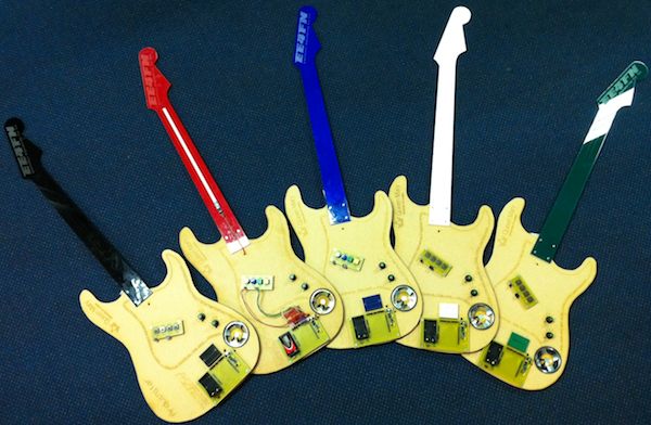
Build Your Own Arduinitar
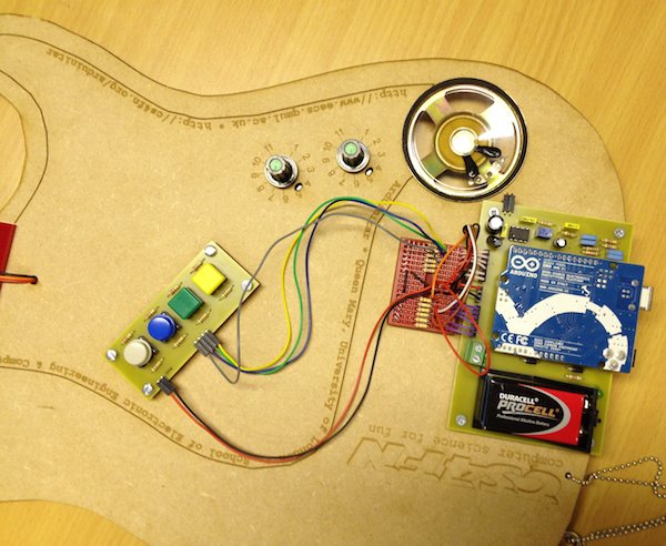
The Arduinitar is a do-it-yourself electronic guitar based on the Arduino microcontroller board. You can build one yourself with an Arduino board and a few other readily available parts. Once you've built it, try changing the circuits or the code to make your own new sounds! These instructions don't assume any specific knowledge of electronics. However, you will want to know or learn how to solder in order to hook up the wires to the sensors (and possibly to build the amplifier board). Likewise, no programming experience is required as the code is available for download (see below), but familiarity with Arduino programming will let you modify the code as you like. OverviewThe Arduinitar uses an Arduino Uno board to make sound. Sensors on the instrument let you control the pitch (frequency), volume (amplitude) and sustain time of each note (see picture). Four buttons let you pluck the virtual "strings" of the instrument, each of which is tuned to a different pitch. When you pluck all four together, you can play chords. Placing a finger on the sensor on the neck will change the pitch of all four strings together (like a slide guitar). To build your own Arduinitar, you need to put together the circuits for reading information from the sensors and for driving the speaker. Then you need to program the Arduino board with the code provided below, which will make it generate the audio for the instrument. Finally, find some solid cardboard, wood or plastic to make the instrument itself! Here are some design files to get you started. These were designed to be used on a laser cutter to cut and engrave the body and neck, but you can also use them to trace the outline by hand.
Required PartsHere's what you need to build an Arduinitar:
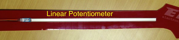
Wiring the SensorsIn this section we'll look at how to wire up the main sensors: the linear potentiometer ("slider") for the neck which controls the pitch of the instrument, the rotary potentiometers ("knobs") that control the volume and sustain time, and the four buttons the pluck the strings. Linear Potentiometer (pitch control)The linear potentiometer (slider) should be attached to the neck of your instrument. Think of its effect like changing the length of your virtual strings, which changes their pitch.
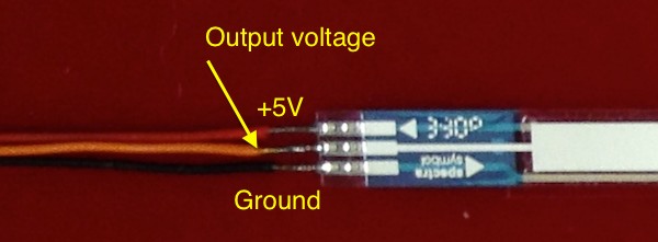
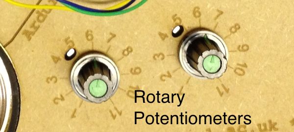
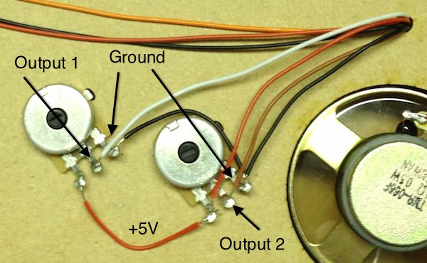
The slider has three terminals at the end. Looking at it from the bottom, the terminal on the left should be attached to +5V. This is your power supply voltage which you will get from the Arduino board; more on that below. The terminal on the right should be attached to Ground (or 0V), which you will also take from the Arduino board. The terminal in the middle is your output voltage. This is an analog electric voltage whose value will range from 0V when your finger is at the very far end of the control (near the guitar head) to 5V when your finger is at the near end (next to the guitar body). Solder some long wires to each terminal of the slider. Be careful when you do this not to heat the metal terminals up too much or the delicate connections inside the sensor might melt. We suggest red for +5V, black for ground and orange for the output. Leave the other ends of these wires unconnected for the moment. Rotary Potentiometers (volume and sustain)These two knobs are attached to the body of the instrument, where you might find them on an electric guitar. One knob will be used to control the volume of the instrument, just like an electric guitar. The other will be used to control how long the strings sustain when you pluck them. Changing this setting will let you create different sounds from the instrument.
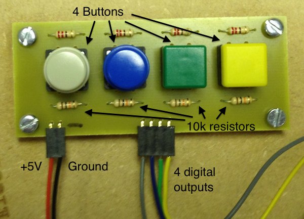
Each knob has three terminals. Just like the slider, when we look at the knob from the back, we will attach the left terminal to +5V (red wire) and the right terminal to Ground (black wire). The middle terminal of each knob will produce an analog voltage (again just like the slider) depending on the knob rotation. All the way counterclockwise is 0V, all the way clockwise is 5V. Use two different colours of wire (we suggest brown and white) for the middle terminals from each of these knobs. If you attach these knobs to the body of the guitar, the wires will be behind the guitar, where your Arduino board is on the front. You may want to make a small hole in the body of the instrument to run the wires from through so they can reach the Arduino board. Buttons (strings)The buttons are digital controls that produce a high value (+5V, logic "1") when pressed and a low value (0V, logic "0") when they're not pressed. In other words, when you press the button, the output will go from low to high. The Arduino code will look for this event and use it to start a new note.
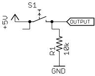
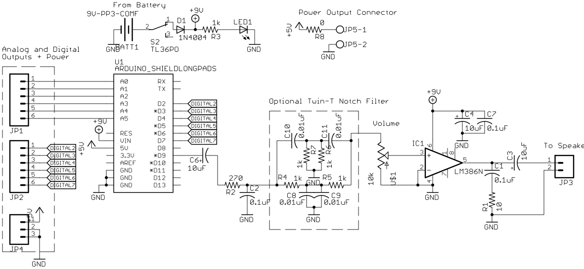
Wiring up a button requires not only the pushbutton switch itself, but also a resistor (see picture and diagram). Attach one end of the switch to +5V and the other end to one side of the resistor. The other side of the resistor goes to Ground. Finally, attach a wire to the place where the switch and the resistor connect. (We suggest matching the wire colours with the colours of the caps on the top of each button.) The idea is that when the button is not pressed, the resistor pulls the output down to 0V, but when the button is pressed, the output is attached to 5V. Again, wiring up the button correctly is going require three wires: +5V (red), Ground (black) and the output. There are four buttons and they should all be wired the same way. You may want to put the buttons on a small circuit board or breadboard to keep them stable. You can use the one +5V wire and one Ground wire for all four buttons, but each button should have a separate output wire. Therefore, if you build your button circuit on a board, you should have six wires coming out: +5V, Ground, and four outputs. Audio CircuitsThe Arduino Uno board, once it's programmed, will create an audio signal on one of its output pins. We need a circuit to filter out some artefacts that come from how the Arduino generates audio, amplify the filtered signal, and then drive a speaker. The diagrams below show an electrical schematic and a suggested wiring layout for the audio circuit. The circuit is based on an LM386 amplifier chip from Texas Instruments. We need this chip because the Arduino by itself does not supply enough power to drive the speaker. The chip has two input pins (+ and -), one output (for the speaker), two power supply pins and some pins for changing the gain of the amplifier. More information on how it works can be found in its datasheet.
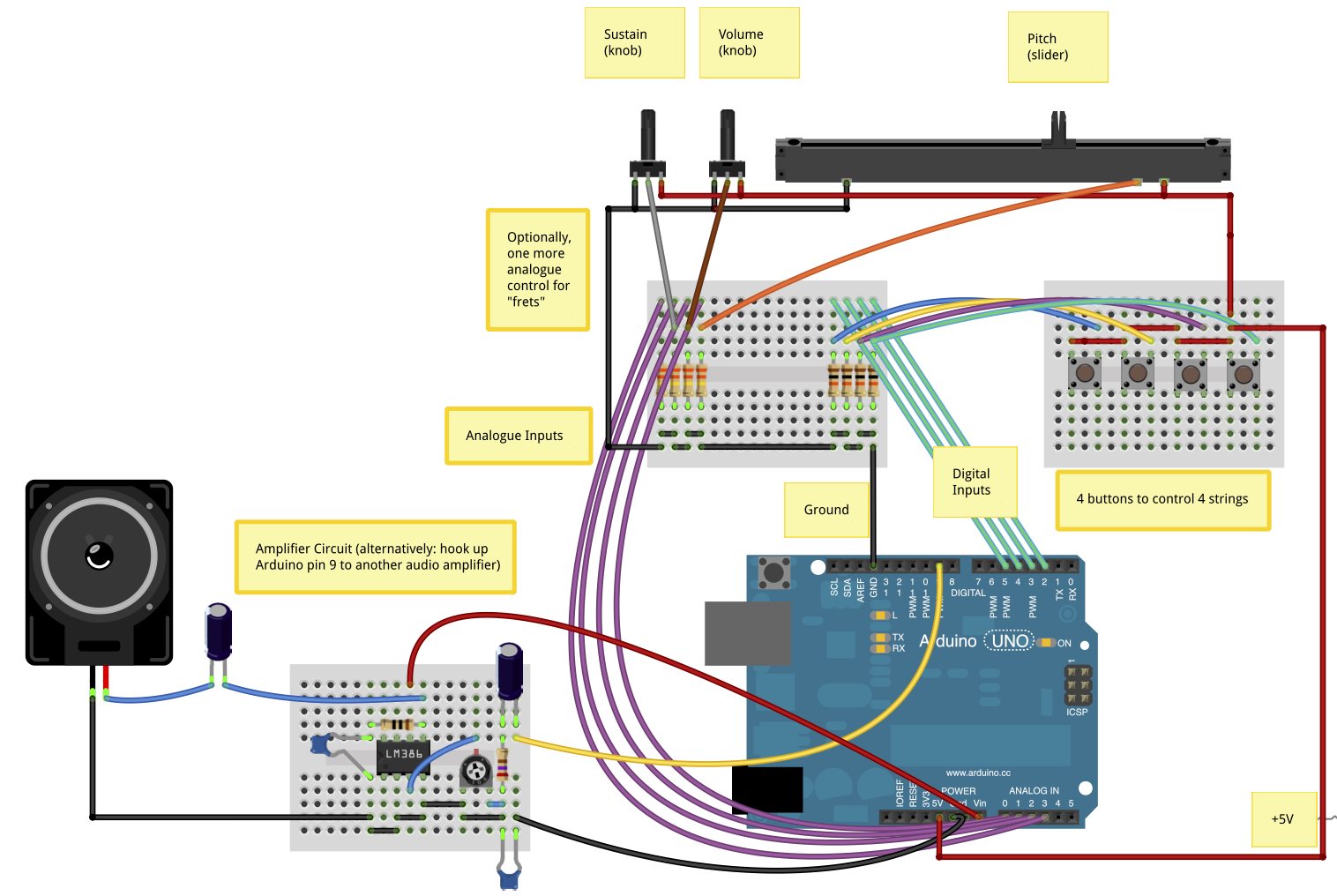
Wiring the audio board will require the LM386, two 0.1uF capacitors, two 10uF capacitors, a 270Ω resistor, a 10Ω resistor and a 10kΩ trimpot (see partslist above). It is most easily built in a breadboard or using a printed circuit board with traces laid out in a similar pattern to a breadboard. However, if you have access to PCB fabrication equipment, you can download design files (see next section) for the amplifier board which includes space for a battery snap, power switch and Arduino Uno. The amplifier board takes three inputs: +5V (or +9V if you use a 9V battery), Ground and Audio In. The Audio In connection comes from Pin 9 of the Arduino Uno board. In turn, the amplifier board connects to the speaker by two wires: Audio Out and Ground. Don't forget to include the 10uF capacitor between Pin 5 of the LM386 and the speaker! Putting It All Together
The next task is to attach all the sensors and the audio circuit to the Arduino Uno, which is going to be responsible for generating the sound. You should have three wires from the analog inputs (slider, two knobs) and four wires from the digital inputs (four buttons). The slider should attach to pin A0 on the Arduino; the two knobs should attach to pins A1 and A2. The code uses pin A0 to determine the pitch of the sound, A1 to determine the volume and A2 to determine the sustain time. The digital inputs should attach to pins 2 through 5 (not to be confused with A2-A5). But see the next section before you wire anything! The audio output of the Arduino is on Pin 9. Attach this pin to Audio In of the amplifier circuit. Finally, make sure the Ground and +5V wires are attached to the corresponding pins of the Arduino. You may have several different wires for each signal, but there is only one or two holes for each on the Arduino, so you will want to connect the wires together externally, for example on a breadboard or a soldered PCB, before bringing one wire to the Arduino. If you have a 9V (PP3) battery, it can be attached to Arduino's power input socket with a special adapter cable. You can also attach the battery leads to Ground (black) and V_in (red) on the Arduino board, but this is not recommended since if you hook it up backwards, you can destroy the Arduino! Our PCB design files use the V_in pin to power the Arduino, and a diode in series with the battery protects it against reverse polarity. Don't leave the battery plugged in when you're not using it, or it will drain quickly. You can disconnect the battery or use a switch to turn the instrument off when not in use.
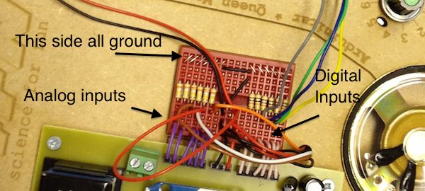
Prototyping BreadboardTo make it easy to experiment with different sensor configurations, we recommend using a solderless mini-breadboard between the Arduino Uno and the wires you have attached to the sensors. If you use a breadboard, then instead of attaching your analog and digital inputs directly to the arduino, plug each wire into one column of the breadboard. Then run another wire from each column to the correct pin on the Arduino. The idea is that you can do all your circuit changes on the breadboard without having to touch the Arduino board itself.
Another advantage of using the breadboard has to do with the analog inputs. If no sensor is attached to a pin on the Arduino, then the value of that pin is undefined. That means that when the Arduino goes to read the sensor voltage from that pin, the reading will be unpredictable and random, and it will lead the instrument to produce strange results. What's more, the linear potentiometer that controls pitch is only connected when you have your finger on it. If you don't press down on the sensor, the output is unconnected and the value of the output will be undefined. For this reason, we run a 330kΩ resistor between each analog input and Ground. This is easily done on the breadboard by attaching the resistors across the gap in the middle of the breadboard. On one side are the inputs from the sensors. On the other side, each column is connected together and then connected to Ground on the Arduino board. These resistors will pull the value of the analog inputs down to 0V whenever nothing is attached, which makes the operation of the guitar much more predictable. The same issue is true with the digital inputs (unconnected or "floating" signals produce undefined results), so one option is to put the 10kΩ resistors you used with the buttons on this breadboard rather than on the same board as the pushbutton switches themselves. But as long as you leave the wires from the buttons connected at all times, you won't have a problem with floating digital inputs. Programming
The Arduino Uno uses a microcontroller to read the sensors and generate the sound. A microcontroller is a small processor which uses considerably less power than a computer CPU but is also significantly slower and more limited. Here we are pushing the edges of the capability of the microcontroller to make it generate audio in real time! The audio generation uses the Mozzi library for Arduino by Tim Barrass. You will need to download the Arduino software and Mozzi before the Arduinitar code will build correctly. Follow the instructions on each page for installing the Arduino software first, and then the Mozzi library. Finally, download the Arduinitar code from the link above. The folder contains two sketches (Arduino programs) which open in the Arduino software. One sketch makes a standard Arduinitar, another is a variation which emulates a bass (four low-tuned strings rather than low, medium and high strings). Once the sketch is open in the Arduino software, click the "Verify" button to test that the code compiles. Finally, with your Arduino board attached to the computer, click the "Upload" button to put the Arduinitar code on the Uno board. Once the circuits are built and the Arduino is programmed, you're ready to go! Push the buttons to pluck the strings and change their pitch with the slider on the neck. Rock on! |